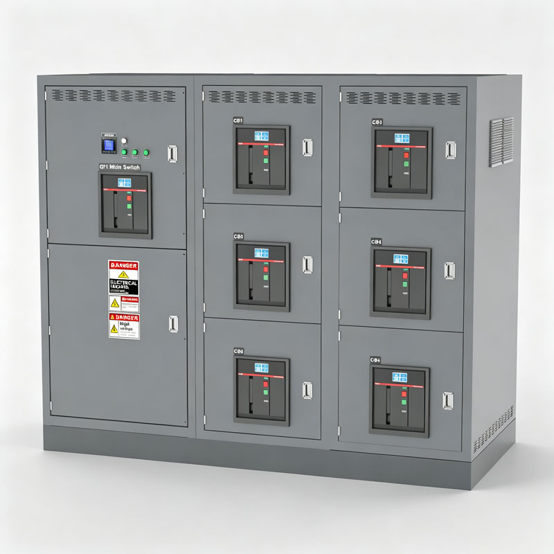
Switchgear
UL1558 /CSA C22.2 No. 31
Professional OEM/ODM Customization Solutions
Switchgear

Switchgear

share

Facebook
Twitter
LinkedIn
Product Introduction

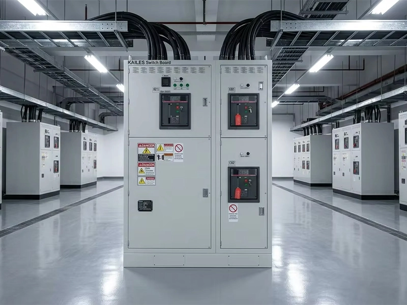
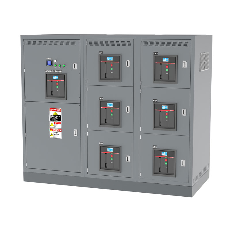
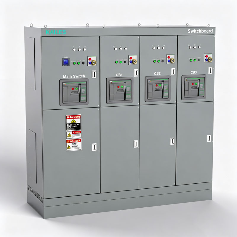
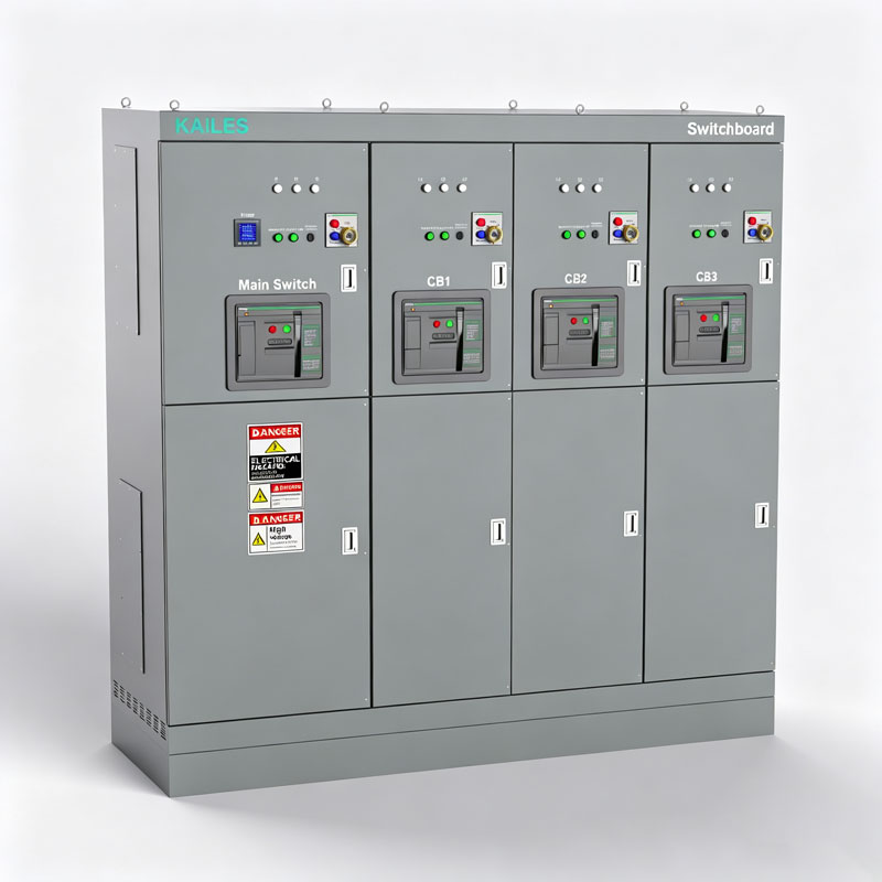
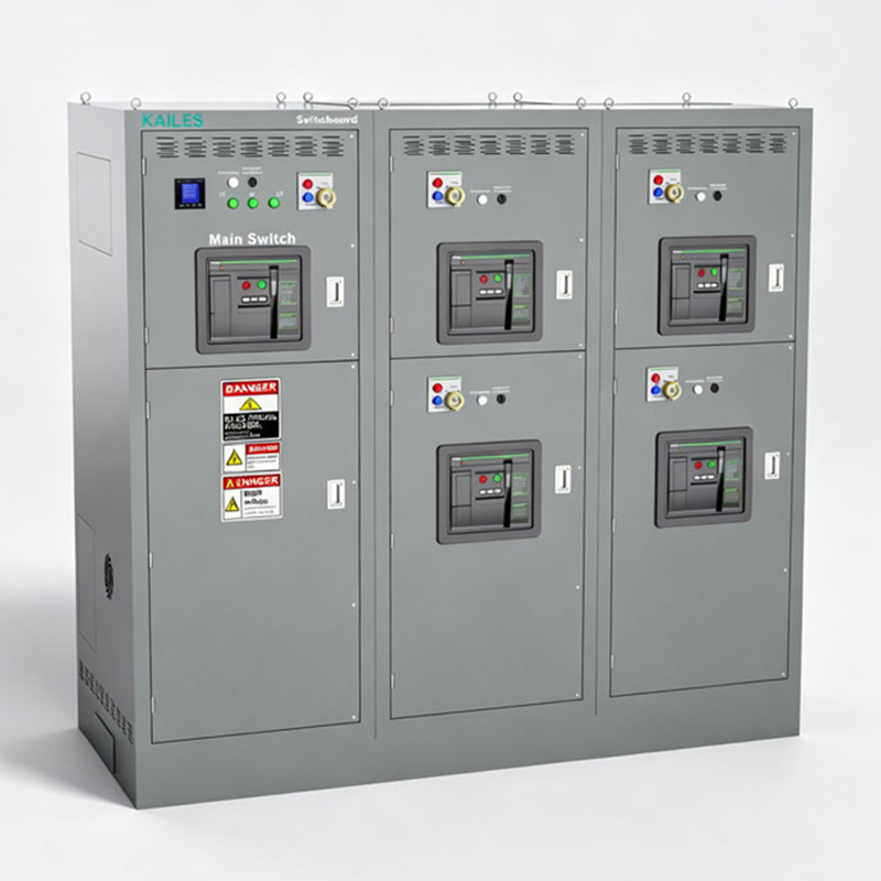
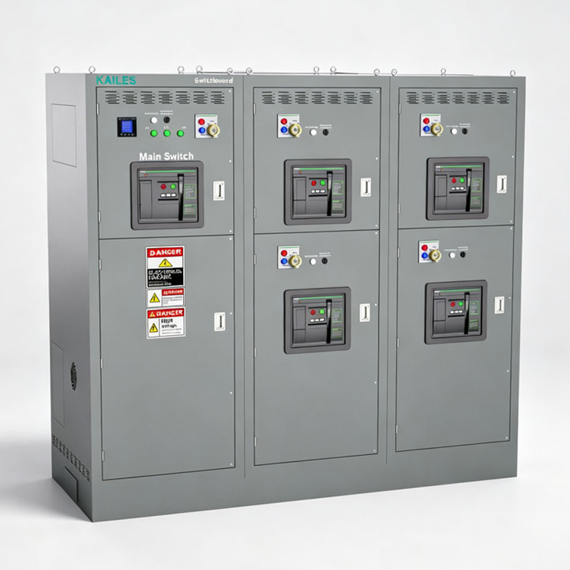
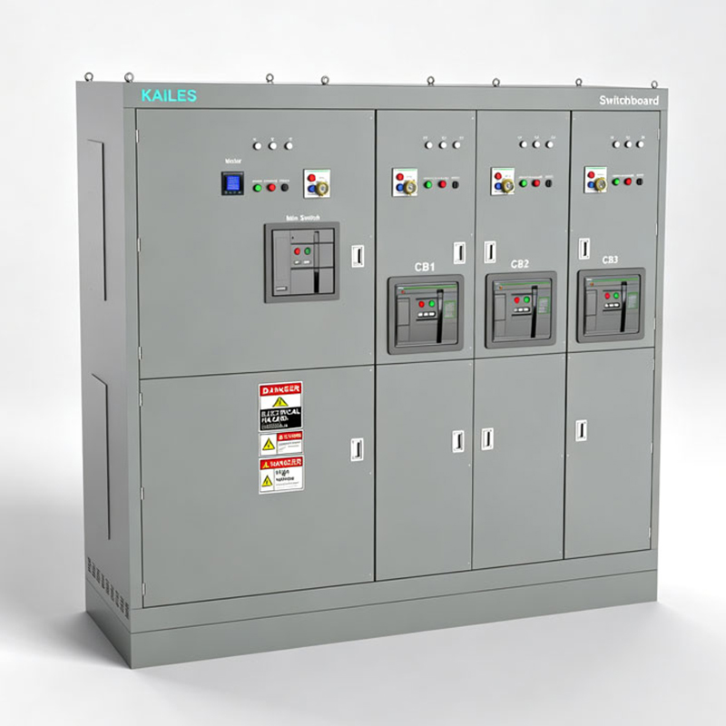
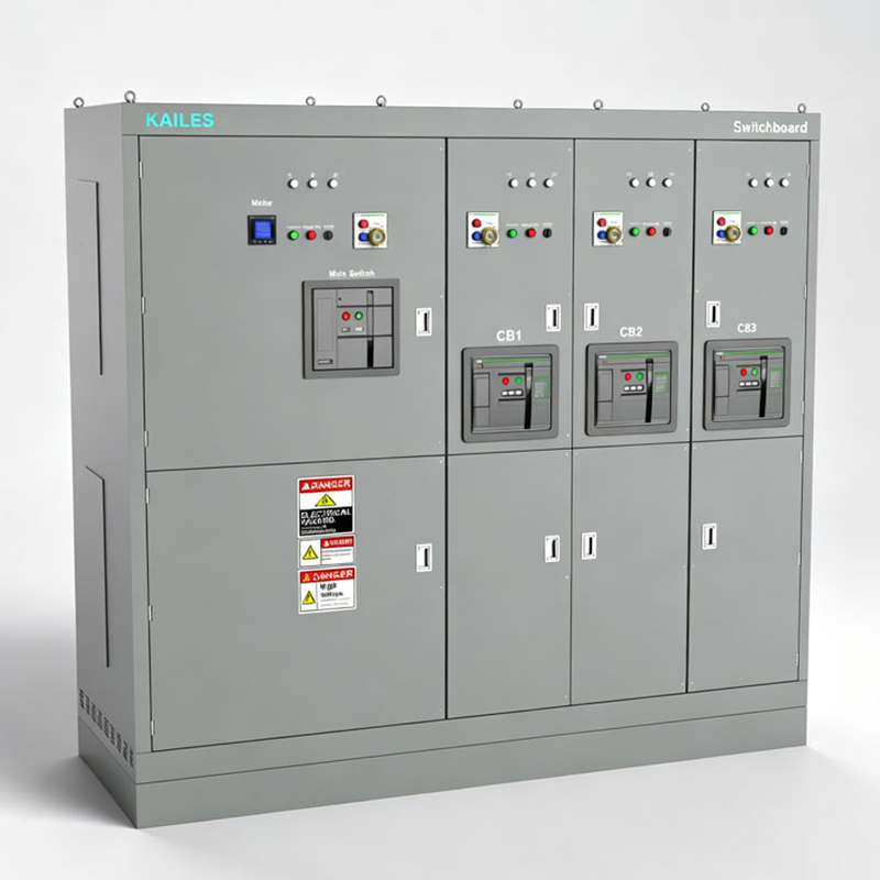
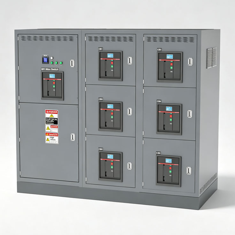
UL 1558 low-voltage switchgear is a metal-enclosed power distribution assembly designed for centralized control, protection, and management of high-capacity electrical systems. It is widely used in data centers, industrial plants, utility facilities, hospitals, commercial complexes, and other mission-critical applications.

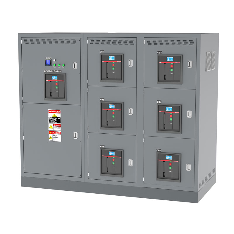
The switchgear incorporates drawout UL 1066 low-voltage power circuit breakers, main busbars, electronic trip units, digital metering, and control systems. Depending on the project, it can provide LSI or LSIG protection, Main-Tie-Main control, ZSI, maintenance-mode protection, power monitoring, and communication functions.

Its compartmentalized and modular construction supports system expansion, selective coordination, inspection, and maintenance. Compared with general-purpose switchboards, UL 1558 switchgear is better suited to applications requiring service continuity, short-time withstand capability, and advanced protection and control. Final ratings and certification claims are subject to the approved product configuration and certification scope.

Product Features
UL 1558 Listed Certification – Compliance for Critical Power Distribution
Designed and manufactured in accordance with UL 1558 requirements for metal-enclosed low-voltage power circuit breaker switchgear. Certified configurations are evaluated through applicable temperature-rise, dielectric, short-circuit, short-time withstand, mechanical operation, and control-circuit tests. Product ratings and listing status are subject to the approved certification scope.
Metal-Enclosed Compartmentalized Construction -Enhanced Safety and Isolation
The switchgear uses metal-enclosed, compartmentalized construction to separate circuit breakers, main busbars, cable terminations, and control equipment. Dead-front barriers, interlocks, shutters, and grounded metal partitions help reduce accidental contact with energized parts and limit the effects of internal faults during operation and maintenance.
Drawout UL 1066 Power Circuit Breakers -Safe and Efficient Maintenance
Equipped with drawout UL 1066 low-voltage power circuit breakers featuring connected, test, and disconnected positions. Electronic trip units can provide LSI or LSIG protection for overload, short-time, instantaneous, and ground-fault conditions. The drawout design supports inspection, testing, and breaker replacement without disconnecting the main power cables.
High Continuous-Current and Short-Time Withstand Capability
Designed for high-capacity distribution systems requiring reliable continuous-current performance and short-time withstand capability. The coordinated bus system, circuit breakers, supports, and connections are engineered to withstand specified fault-current levels while supporting selective coordination and service continuity. Final current and withstand ratings are determined by the certified configuration.
Modular Intelligent Platform -Flexible Protection and Control
The modular platform supports Main–Tie–Main arrangements, automatic transfer and control logic, digital metering, power-quality monitoring, ZSI, maintenance-mode protection, and optional communication interfaces. Modbus TCP/RTU, Ethernet gateways, remote I/O, and energy-management functions can be integrated according to project requirements.
Mission-Critical Reliability-Designed for Service Continuity
Compared with general-purpose switchboards, UL 1558 switchgear is better suited to applications requiring advanced protection, selective coordination, short-time withstand capability, and rapid maintenance. Its modular drawout construction helps reduce maintenance downtime and supports reliable operation in data centers, hospitals, industrial plants, utility facilities, and other mission-critical power systems.
Switchgear
Product Image Display
Low Voltage Distribution System
Switch gear Technical Selection Table  (Core Technical Parameter Selection Table for LV Switch gear
Dimension UL 1558 Standard  Technical Options IEC 61439-1/2 Standard  Technical Options
Standards UL 1558, CSA C22.2 No. 31, NEC (NFPA 70),IEEE C37.20.1,ANSI/IEEE C37.51 IEC 61439-1/2, EC 60947-2,  IEC 60909, IP Ratings
Rated Voltage 600V, 480V, (Up to 1000V DC/AC)
Rated Current 1000A, 1200A, 1600A, 2000A, 2500A, 3200A, 4000A, 5000A, 6000A 1000A, 1250A, 1600A, 2000A, 2500A, 3150A/3200A, 4000A, 5000A, 6300A, (Customized up to 8000A)
Frequency 50Hz / 60Hz  (Universal Global Frequency (50/60Hz) compatible.)
System Type 3-Phase 3-Wire (3P3W) / 3-Phase 4-Wire (3P4W)  (Optional Neutral Bus (Configurations available with or without neutral).
SCCR & Icw 65kA, 85kA, 100kA, 150kA, 200kA (@415V/480V) 50kA, 65kA, 85kA, 100kA, 150kA (@415V/480V)
Busbar Material Tin-plated/Silver-plated Copper (Standard Tin-Plated or Silver-Plated Finish for superior oxidation resistance.)
Enclosure Rating NEMA 1  NEMA 3R , NEMA 4X IP54, IP65
Dimensions (H×W×D) Variable Enclosure Dimensions optimized for different current ratings.
Cable Entry Customizable Top and Bottom Cable Entry or Exit for flexible installation.
Enclosure Material High-quality Galvanized Steel Sheet.  /  SS304 Stainless Steel
Breaker Brand Schneider, ABB, Eaton, Siemens,LS, Noark, or KAILES Standard
Smart Monitoring Smart Power Meter with Harmonic Analysis & Modbus/TCP Communication


Installation Guide

Front Working Space Depth

Provide the working-space depth required by NEC Table 110.26(A)(1), based on the system voltage-to-ground and the condition opposite the switchgear.

For typical systems rated 151–600 V to ground:

Condition 1: Minimum 3 ft (0.91 m)

Condition 2: Minimum 3.5 ft (1.07 m)

Condition 3: Minimum 4 ft (1.22 m)

For systems rated 150 V or less to ground, the minimum depth is generally 3 ft. Final clearance must be verified against the locally adopted NEC edition and site conditions.

Width and Height of Working Space

The working-space width must be at least 30 inches (762 mm) or the width of the switchgear, whichever is greater. Equipment doors and hinged panels must be capable of opening at least 90 degrees.

The clear working-space height must be at least 6 ft 6 in (1.98 m) or the height of the switchgear, whichever is greater.

Access and Egress for Large Equipment

Where switchgear rated 1200 A or more and wider than 6 ft (1.83 m) meets the conditions of NEC 110.26(C)(2), an entrance to and egress from the working space is generally required at each end.

Applicable NEC exceptions may permit a single entrance where the working-space depth is increased or where an unobstructed exit path is provided. Final room layout must be approved according to the locally adopted code.

Personnel Doors and Panic Hardware

Where the applicable conditions of NEC 110.26(C)(3) are met for equipment rated 800 A or more, personnel doors located within the specified distance of the working space must:

Open in the direction of egress;

Be equipped with listed panic hardware or listed fire-exit hardware;

Provide a clear and unobstructed escape path.

This requirement is conditional and should not be described as mandatory for every UL 1558 installation.

Dedicated Electrical Space

For indoor installations, provide dedicated electrical space equal to the width and depth of the switchgear, extending from the floor to 6 ft (1.83 m) above the equipment or to the structural ceiling, whichever is lower.

Foreign systems such as water piping, drainage piping, and HVAC ducts should not be installed within this dedicated zone. Code-compliant sprinkler protection may be permitted when installed in accordance with the applicable NEC requirements.

Rear Access, Foundation, and Anchorage

For rear-access switchgear, provide the rear working space required for the actual maintenance activity:

If examination, adjustment, servicing, or maintenance may expose energized parts, apply the working-space requirements of NEC 110.26;

If rear access is required only for nonelectrical parts, provide at least 30 inches (762 mm) of horizontal working space where required;

Follow the manufacturer’s drawings for escape aisles, cable access, ventilation, and door clearances.

Front-access-only switchgear may be installed closer to a wall only when permitted by the listed equipment design and manufacturer’s instructions. Install the lineup on a level concrete pad and anchor it according to the approved seismic and structural requirements.

KAILES: One-Stop Service System from Design to Global Delivery
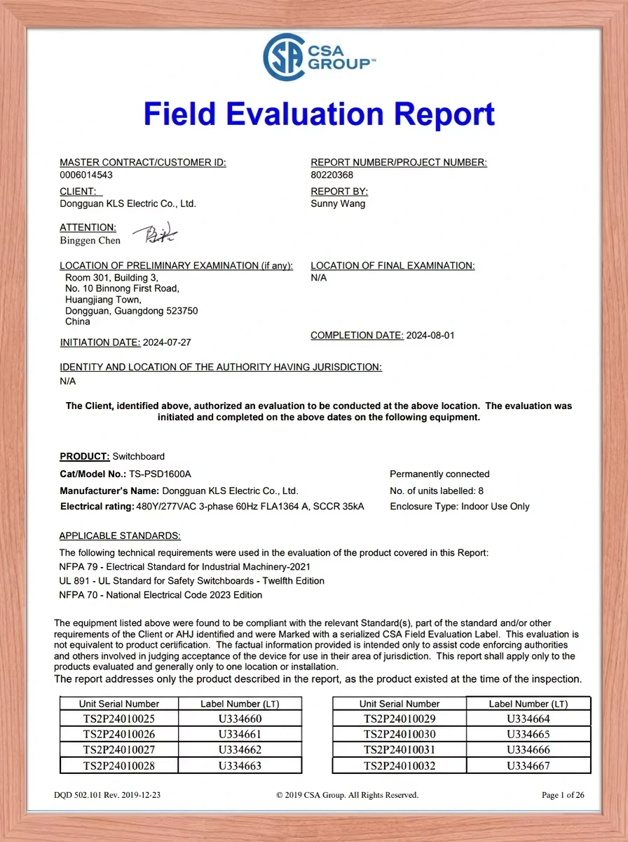
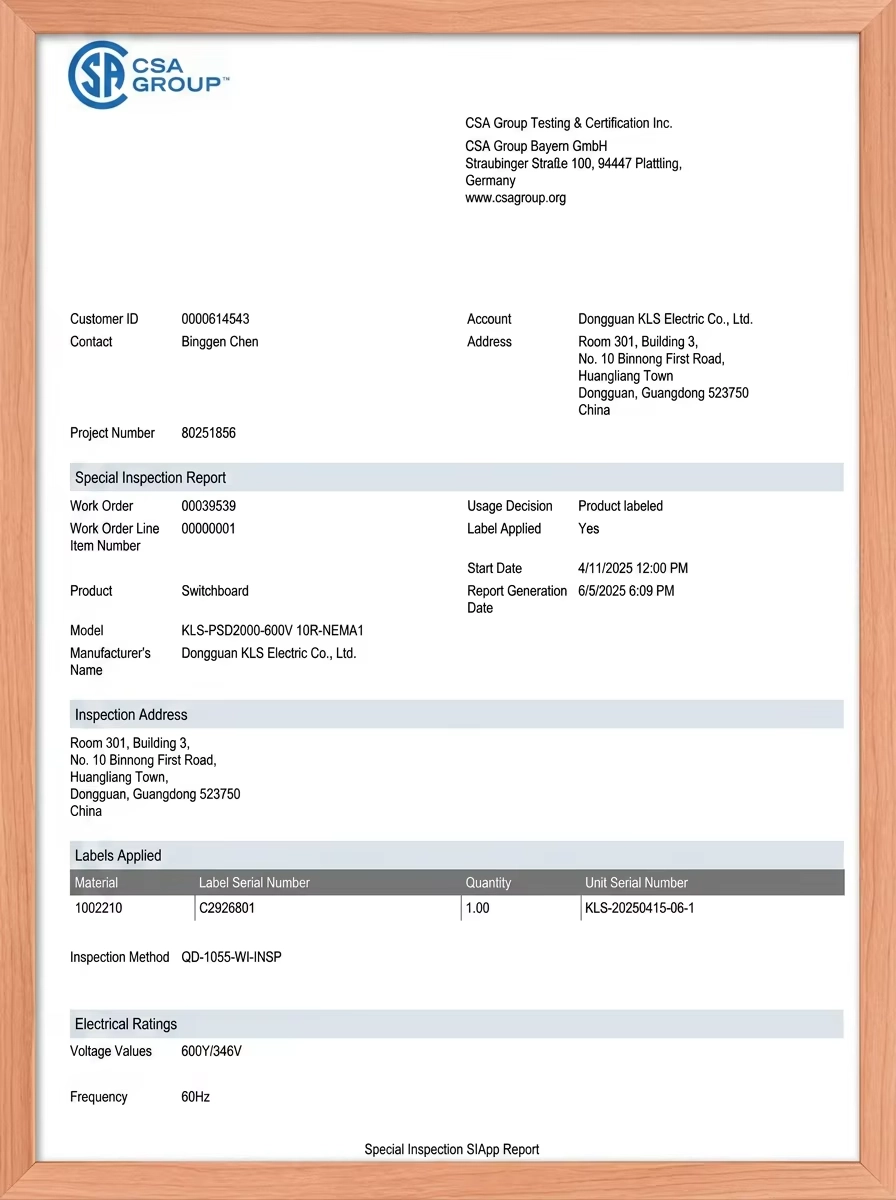
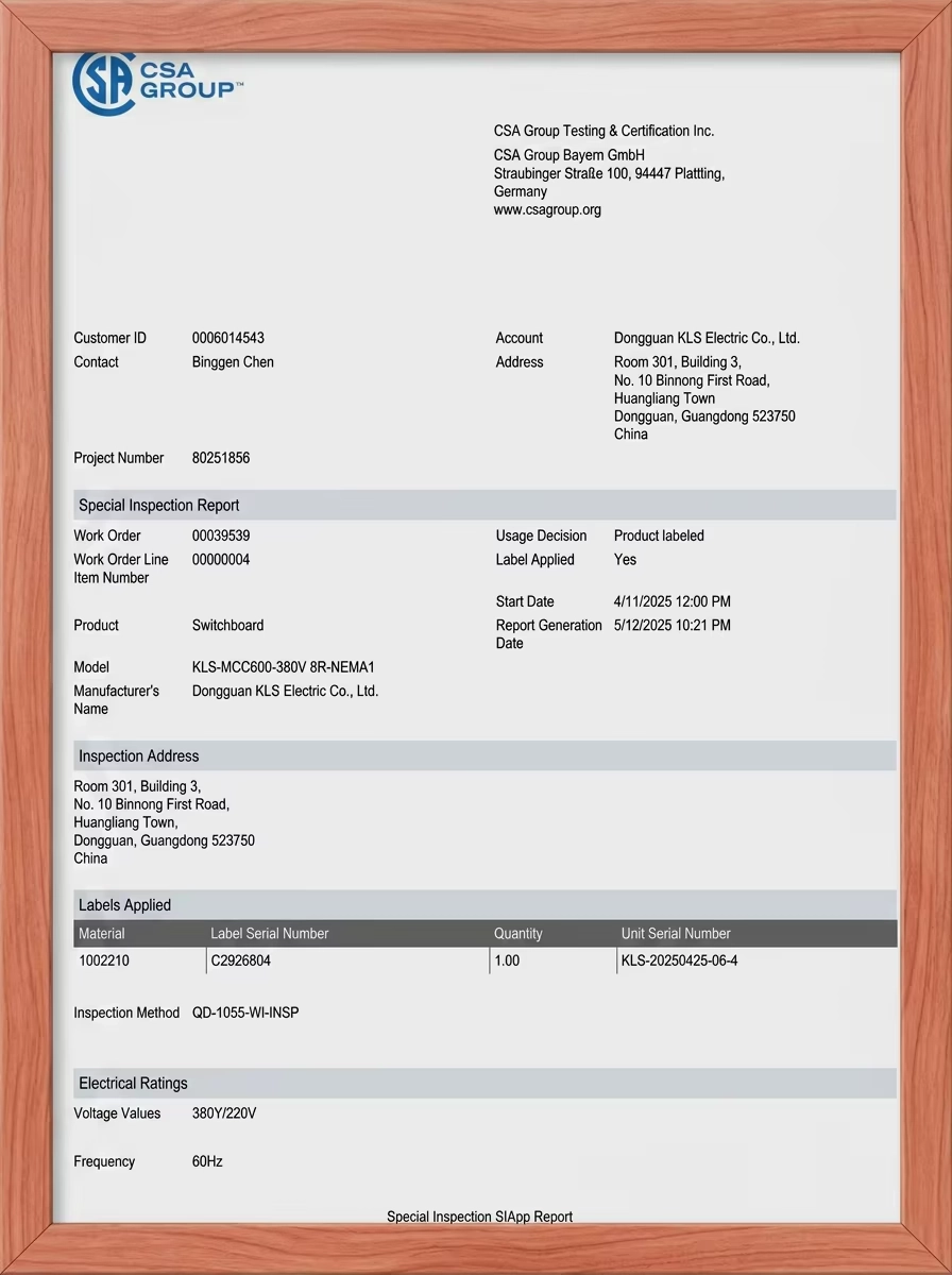
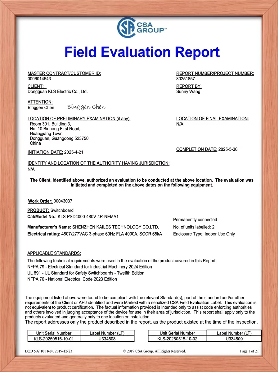
Certification Certificate
Frequently Asked Questions
Experiential Marketing
Which standards are available for your low-voltage switchgear?
We offer separate regional configurations designed for different markets: ANSI/UL 1558 for the United States, CSA C22.2 No. 31 for Canada, and IEC 61439-1/-2 for IEC-based markets. UL 1558 configurations are coordinated with IEEE C37.20.1 and ANSI C37.51, while installation is subject to NFPA 70 (NEC) and local AHJ requirements. Final certification coverage depends on the specific model, ratings, components, and manufacturing location.
Can I specify the circuit breaker brand?
Yes. Depending on the certified configuration, we can integrate approved UL 1066 low-voltage power circuit breakers from brands such as ABB, Eaton, Schneider Electric, and Siemens. Drawout circuit breakers are commonly used to support connected, test, and disconnected positions. The final brand, model, ratings, and accessories must be confirmed against the certification scope.
What is the typical production lead time?
Standard switchgear configurations typically require approximately 8–10 weeks. Customized multi-section lineups with special protection, control, communication, or certification requirements may require approximately 12–14 weeks. The confirmed production schedule will be stated in the formal quotation after the technical scope is finalized.
Can the cable-entry direction be customized?
Yes. Top or bottom cable entry can be provided, while side entry may be accommodated through an approved cable or pull section. Please provide the conductor material, cable size, number of parallel cables, conduit arrangement, bending-radius requirements, and entry direction before the design is finalized.
What busbar materials and finishes are available?
High-conductivity copper busbars are commonly used, with tin-plated or silver-plated connection surfaces available for improved oxidation resistance and connection reliability. Aluminum busbar configurations may also be offered where covered by the approved design. Busbar material, dimensions, plating, continuous-current rating, and short-time withstand rating are determined for each project.
What installation space is required?
Installation space must comply with the locally adopted NEC, manufacturer instructions, and AHJ requirements. Under NEC 110.26, the front working depth is commonly 36, 42, or 48 inches, depending on voltage-to-ground and the condition opposite the switchgear. Rear-access equipment requires appropriate rear working space, while front-access-only configurations may be installed closer to a wall where permitted by the listed design. Large lineups may also require additional access and egress provisions.
What is the warranty period?
Our standard warranty is generally 12–24 months from the date of shipment, depending on the product configuration and contract terms. Extended-warranty options may be available. The warranty period, covered components, exclusions, freight responsibility, and service conditions will be clearly stated in the formal quotation or sales contract.
How do you provide technical and after-sales support?
We provide remote troubleshooting, technical documentation, wiring and test-record review, replacement-component support, and video-guided service assistance. Where replacement parts are required, shipment and response arrangements are handled according to the agreed service terms. On-site support and emergency response can also be evaluated for specific projects.
Contact us

Committed to providing customers with intelligent, safe and reliable power distribution solutions.

Wechat